Alexan

ACE-N-553640-82 ESP8266 Wifi 8 Channel Relay Module ESP-12F Development Board Power Supply 5V/7-28V Wireless Wifi Module

ACE-N-553640-82  8 Channel Relay Module ESP-12F Development Board Power Supply 5V/7-28V Wireless Wifi Module ESP8266

Description:

This CE-N-553640-82 ESP8266 WIFI 8-Channel Relay Module ESP-12F Development Board is perfect for Arduino development environment with reference code and is suitable for ESP8266 secondary development and learning, smart home wireless control and other occasions.

It is an ideal solution for home automation, remote control, sensor networks, industrial control, and other IoT applications. The 8-channel relay can be controlled by WiFi Net, iOS/Android App, and web page. It can be used to control lights, electrical equipment and other appliances remotely.

The product is easy to set up and use, and comes with a detailed user manual. It has an integrated high-precision 10A AC/DC dual-channel optical coupling isolation module and a power-on self-test function. With this product, you will enjoy the convenience of smart home control.

  • Feature:
  • 1. Onboard mature and stable ESP-12F WIFI module, large capacity 4M BYTE FLASH;
  • 2. The power supply mode supports DC7-28V/5V;
  • 3. The onboard Wi Fi module RST reset button;
  • 4. ESP-12F supports development tools such as Eclipse/Arduino IDE, and provides reference programs for Arduino development environment;
  • 5. Provide reference programs under the Arduino development environment;
  • 6. There are 8 channel 5V relays on board, which output switch signals, suitable for controlling loads whose working voltage is within AC250V/DC30V;
  • 7. Onboard power indicator and relay indicator.
  1. The Board
    The microcontroller is an ESP8266 12F and can be programmed with the Arduino IDE. I use the settings of the Node MCU 0.9 for the upload.
  2. 8 relays are connected to GPIOs. The outputs are HIGH active. The relays are connected to GPIO16, GPIO14, GPIO12, GPIO13, GPIO15, GPIO0, GPIO4 and GPIO5. On startup GPIO16 and GPIO15 will be active for a very short time – you will hear the two relays. Take this in consideration when you use these two relays as outputs.
  3. GPIO0 and GPIO2 are available on a separate header, but remember, that GPIO2 is also connected to the (blue) LED on the ESP itself. The ADC is also available on the header. You can solder a header to gain access to following pins:
  • 5V
  • TXd – GPIO1
  • RXd – GPIO3
  • IO0 – GPIO0 – connect to GND and reboot (power cycle) if you need to set the ESP8266 in flash mode
  • GND
  • GND
  • IO2 – GPIO2 – also used for the (blue) LED on the ESP8266
  • ADC – A0 – the analog input of the ESP8266
SKU: ACEN553640-82 Category: Tag:

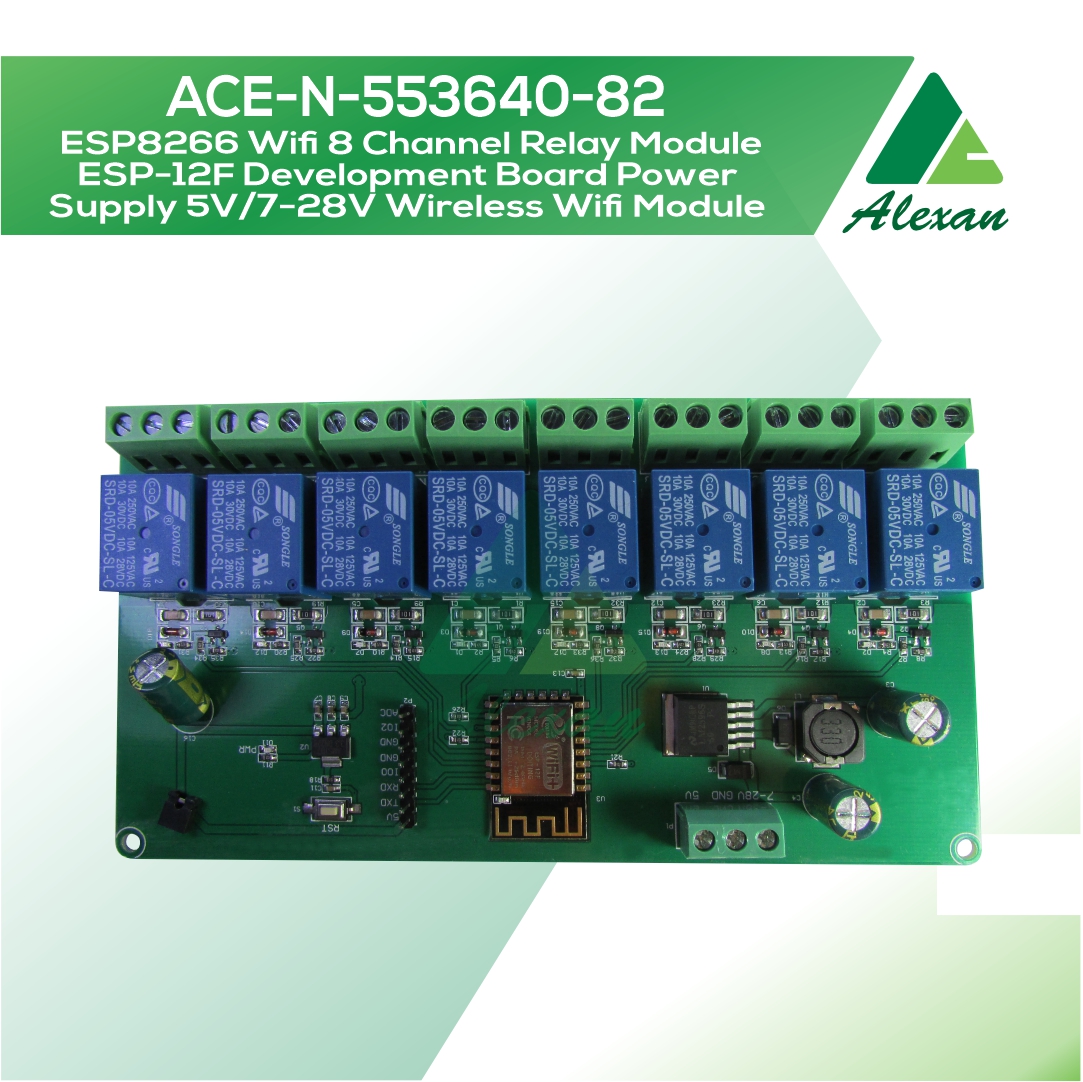
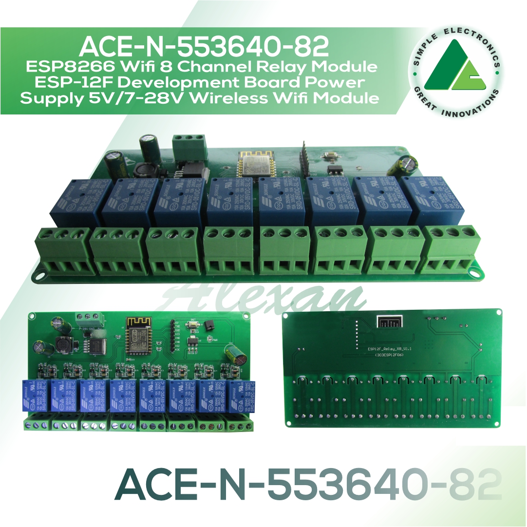
ACE-N-553640-82 ESP8266 8 Channel Relay Module ESP-12F Development Board Power Supply 5V/7-28V Wireless Wifi Module

Specifications:
1. Work voltage: DC 5V/DC 7-28V
2. Work Temperature: -25℃~85℃
3. Work Humidity: 5%~95%RH
4. Size: 149*80mm

Burning port:
The GND, RX, TX, and 5V of ESP8266 are respectively connected to the GND, TX, RX, 5V, of the external TTL serial port module, IO0 needs to be connected to GND when downloading, and then disconnect the connection between IO0 and GND after downloading.

The 6 pins of the ESP8266 12F lower side are not connected to the PCB. If you need to use these IOs (11, 7, 9, 10, 8, 6), you have to solder them directly to the ESP.

The board can be supplied with DC 5V or DC7-28V. A step down converter LM2596S regulates the voltage to 5 V, and a smaller one is used to generate the 3.3V for the ESP8266. When all 8 relays are active, the board draws around 700mA @ 9.6V.

The board has cutouts between the relay pins, nevertheless don’t use these relays with mains electrics/230V
The dimension of the board is 148 * 79.8 * 19mm.


Dimensions 148 × 49.8 × 19 mm